The FVA-Workbench is a manufacturer-neutral tool for the simulation and calculation of transmission systems. As product development cycles become shorter, powerful modeling approaches and calculation algorithms become increasingly important. The predominantly analytical approaches in the FVA-Workbench deliver fast and reliable solutions to all important issues related to drive technology. For bodies that cannot be well described analytically, the results are supplemented by numerical methods. The intuitive modeling techniques in the FVA-Workbench guarantee consistent, valid, and manufacturable gears every time.
The calculations are developed, analyzed, and validated in research projects by Forschungsvereinigung Antriebstechnik e.V. (FVA, the German Research Association for Drive Technology). Through membership fees and public funding, the FVA is able to organize 14 million euros annually in research projects at leading German universities, chairs, and research institutions. The FVA-Workbench serves as a platform to make this knowledge accessible to all engineers.
Precise load carrying capacity calculations can be used to determine the stress, load carrying capacity, damage sums, and other characteristics of bevel gear stages. The load-free contact simulation, in particular, has the potential to significantly influence the design process.
The starting point for every calculation is the exact surface of bevel and hypoid gears and their position relative to each other. The descriptions of the tooth flank and tooth root are generated in a manufacturing simulation, taking machine settings and manufacturing deviations into account. Compensation areas are used to transform this discrete point cloud into a gapless mathematical description of the tooth surface.
The load-free tooth contact simulation is the core component of the rolling contact simulation, and can efficiently determine the key parameters of the gear. Relevant evaluation criteria include: the ease-off, the load-free working variation, the load-free contact pattern, determination of the backlash, and the axial retractability of the pinion (FVA Research Project 456 II ”BECAL - Backlash and Retractability,“ TU Dresden IMM, Prof. Dr. Schlecht).
The circumferential backlash is chosen based on the gear parameters, production quality, and the relative position deviations to be expected under load. This prevents meshing interference and gear jamming. Too little backlash can lead to jamming due to relative position deviations under load, too much can lead to increased noise and reduced load capacity.
In addition to the microgeometry, the mounting position, relative position deviations under load, and specified pitch deviations of the working and trailing flanks are considered when calculating the backlash.
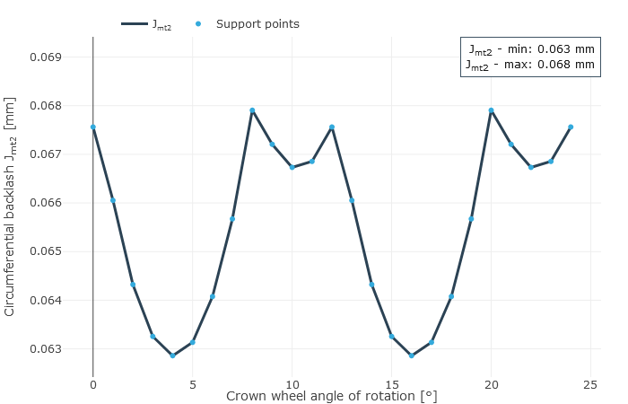
In practice, bevel gears always include flank modifications. Therefore, the backlash is not constant when considered across the meshing positions (see Figure 1). The difference between the minimum and maximum backlash is caused by superposition of the working variations in drive and coast operation. The theoretical foundation for the backlash calculations was developed and implemented in FVA Research Project 223/XVIII (”BECAL – Operating Clearance,“ TU Dresden IMM, Prof. Dr. Schlecht). The influences related to backlash calculation are being reassessed in ongoing research projects in order to better reflect the actual conditions under load.
Evaluation of the retractability of the pinion is another application for the circumferential backlash calculation. A pinion is retractable if it can be rotated out of the mesh and the pinion only moves along the gear axis. The relative position of the axis of the pinion only changes in the axial direction out of the mesh as a result. Retractability refers to both the mounting and disassembly procedures. This has an enormous influence, especially on the design of the casing. The question of whether or not the bevel pinion is axially retractable significantly influences the mounting and disassembly processes.
Retractability is calculated from the backlash. Therefore, the exact tooth form, including microgeometry and manufacturing deviations, is also taken into account here. The cutter head radius rc0 has the greatest influence on the retractability, as it determines the curvature of the flank in the longitudinal direction. This should be the very first thing to be adjusted in order to optimize the retractability. A larger cutter head radius increases the retractability, but is limited by economic considerations and a change in the displacement behavior, and therefore cannot simply be increased as desired.
| Basic geometry parameters | Pinion | Crown wheel |
| Number of teeth | 15 | 43 |
| Normal module | 3.18 mm | |
| Shaft angle | 90° | |
| Hypoid offset | 0.0 mm | |
| Face width | 35 mm | 35 mm |
| Average pinion cone distance | 88.41 mm | 88.41 mm |
| Average helix angle | 35° -35° |
In the FVA-Workbench, the minimum and maximum backlash over the axial displacement of the pinion are graphically represented as a result of the retractability calculation. The following three cases can occur:
The retractability results for a bevel gear with the basic geometry described in Table 1 are summarized in Figure 3.
Without retractability, the pinion can be mounted by placing it into the mesh in the axial direction of the crown wheel axis, or by lowering the crown wheel if the design allows (axial displacement of the crown wheel out of the mesh). Axial retractability of the pinion can be achieved under these conditions (see Figure 3). In this case, it should be verified that the value specified for the lowering of the crown wheel is sufficient for the retractability calculation.
Calculation of retractability in the design phase makes it possible to draw important conclusions on the design as well as the requirements for the gearbox environment (casing). If the pinion is not retractable in the initial bevel gear design, the design can be adapted until retractability is achieved. The FVA-Workbench can quickly and efficiently calculate the effectiveness of these changes.
