
Practice-Oriented Determination of the Longitudinal Load Distribution of Planetary Stages
The goal of increasing the power density of a gear unit demands that extraneous material reserves can be detected and reduced to the necessary level. In this context, it is important to know the influences acting on the gear unit and the resulting loads. Precise knowledge of the longitudinal load distribution in the gear meshes during operation, and specification of suitable microgeometries for its optimization, play a decisive role.
In the following, the example of a planetary cylindrical gear unit from the FVA Nacelle Research Project [1], as typically used in wind turbines with an output up to 1.5 MW, will be used to demonstrate the realistic determination of the longitudinal load distribution in the planetary stages and calculation of the required face modifications with the FVA-Workbench. In doing so, the influence of the stiffness of the planet carrier will be quantified and taken into consideration.
Calculation of the longitudinal load distribution of planetary stages
The longitudinal load distribution of a planetary stage is primarily determined by the following influencing factors:
- Torsional deformation of the sun gear
- Deflection of the planet pins
- Twisting of the planet webs (for dual-plate planet carriers)
- Deflections and clearances of the planetary bearings (especially with helical gears)
The torsional deformation can be effectively calculated with the formulas specified in the standards. Likewise, the bending deformation of the planet pin can also be effectively estimated. These two deformation types make up the primary influences on the longitudinal load distribution in simplified calculation processes, which are largely based on the methods described in the load capacity standards.
However, the deformation behavior of the planet carrier cannot be described with sufficient accuracy using these simplified formulas. The Finite Element Method must be applied to obtain realistic results.
Furthermore, with helical planetary gears, the opposing axial forces in the sun-planet and planet-ring gear meshes lead to tilting of the planets within the elastic bearing deflections and the radial clearances of the planetary bearings. Once again, there are no formulas in the standards for detailed estimation of these amounts based on the bearing geometry and the load distribution in the bearing.

Figure 1: tilting of the planet gear
Consideration of planet carrier deformation in the FVA-Workbench
There are four different options in the FVA-Workbench for considering the planet carrier deformation:
Option 1: The webs of the planet carrier are simplified as torsionally stiff solid discs. For dual-plate planet carriers, the torque is transferred between the two webs via the bolts. An additional torsional stiffness between the webs can also be specified if it is available from measurements or external calculations.
Option 2: The planet carrier is modeled in the FVA-Workbench by approximating the webs and bolts as solid discs and shafts, respectively. For dual-plate planet carriers, different strut shapes between the two webs can also be defined. This geometry is automatically meshed within the FVA-Workbench, and the planet carrier deformation is then calculated with the Finite Element Solver [2].
Option 3: If a fully-designed planet carrier is available as a CAD file, it can be loaded in the FVA-Workbench. Here, too, the meshing is automated with subsequent calculation of the deformation using the FE method. Figure 2 shows an example of a deformed planet carrier and the resulting deflection of the planet pins.
Option 4: If the planet carrier deformation has already been calculated externally, the determined deformation behavior can be considered in the FVA-Workbench by importing a reduced stiffness matrix in Harwell-Boeing format.
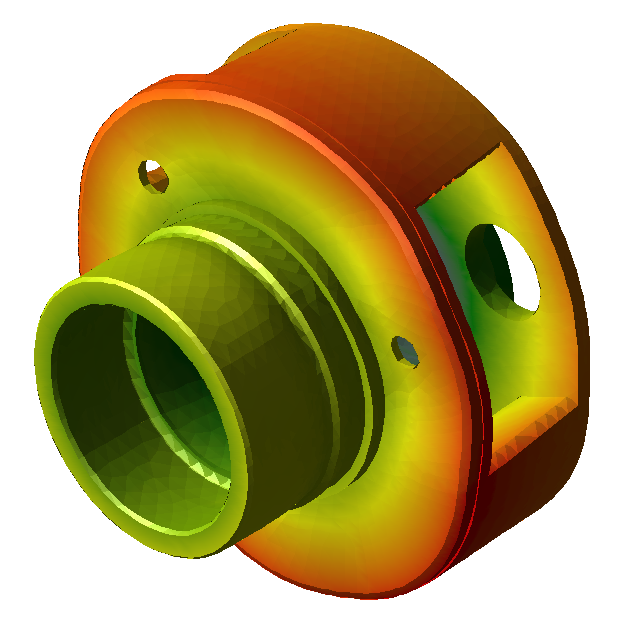
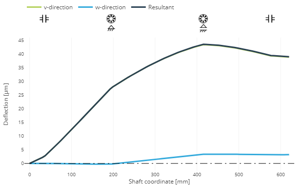
Figure 2: deformed planet carrier (left) and planet pin deflection (right)
The accuracy of the results of the component calculations using the FE method greatly depends on the selection of suitable boundary conditions and the meshing. In the FVA-Workbench, the meshing of the component and definition of the coupling points is largely automated (one-click FEM method) and is adapted to the specific gearbox components to be calculated. Components are loaded and positioned in the 3D Model, with the system providing user guidance for support. This method ensures that reliable and reproducible results can be achieved, even without special FE knowledge.
Calculation of rolling bearing stiffness and operating clearance in the FVA-Workbench
In the FVA-Workbench, the stiffness and operating clearance of rolling bearings are calculated using methods developed in FVA research projects [3,4]. These are based on detailed analysis of the contact between the rolling elements and the bearing rings. As part of these research projects, the methods were validated by test stand experiments and by comparing the results to those of the bearing manufacturers.
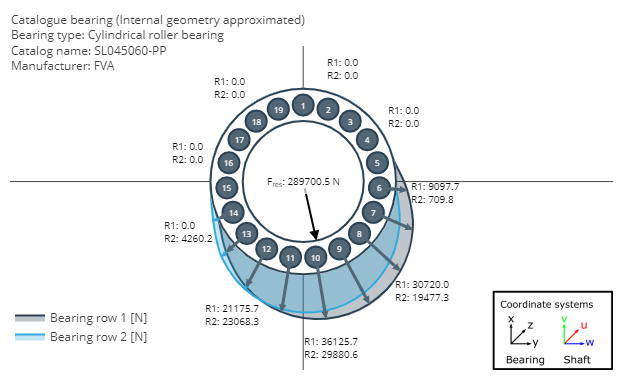
Figure 3: load distribution in a planetary bearing
Calculation example
Below, the gearbox model from the FVA Nacelle Research Project [1] is used to demonstrate the importance of a detailed deformation analysis for calculation of the longitudinal load distribution and the design of face modifications for planetary gears.
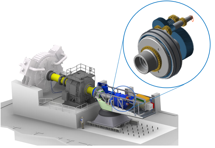
Figure 4: FVA Nacelle Research Project [1] test stand setup and FVA-Workbench gear model
Figure 5 compares the longitudinal load distribution of the planetary stage in the sun-planet mesh for three different calculation variants:
Variant 1: Here, the longitudinal load distribution is shown based on a simplified calculation, without consideration of the deformation of the planet carrier and deflection of the planetary bearings, as is still often used in simplified methods. In the FVA-Workbench, the torsional stiffness of the planet carrier and the radial stiffness of the planetary bearings can be set to a very high value. It can be seen that the torsional deformation of the sun gear (blue area) is dominant compared to the tilting of the planets (green area). This method produces a calculated overload at the generator-side end of the gear.
Variant 2: An additional face modification in the form of a helix angle modification with symmetrical crowning is considered in this calculation. This face modification is designed to produce a uniform load distribution when combined with the deformations from the simplified calculation in Variant 1.
Variant 3: This longitudinal load distribution is the result of the detailed calculation of the deformations of the planet carrier and the planetary bearings, which are to be compensated by the flank modifications determined from the simplified calculation. In this case, it can be seen that the greater tilting of the planet gear leads to a local overload on the rotor-side end of the gear.
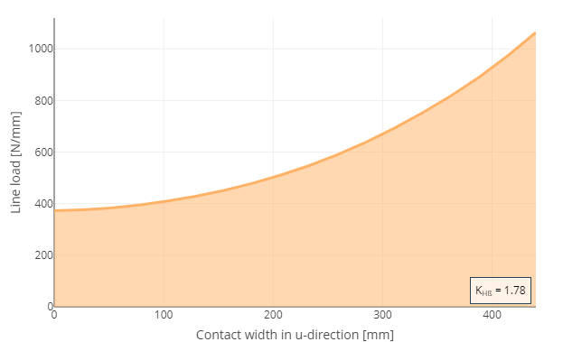
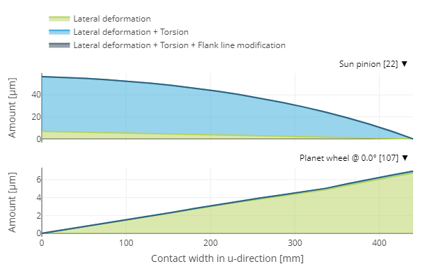
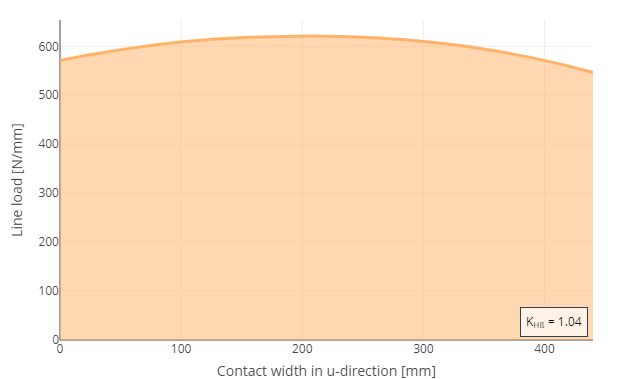
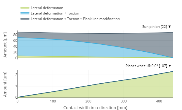
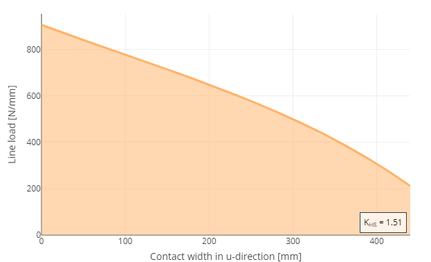
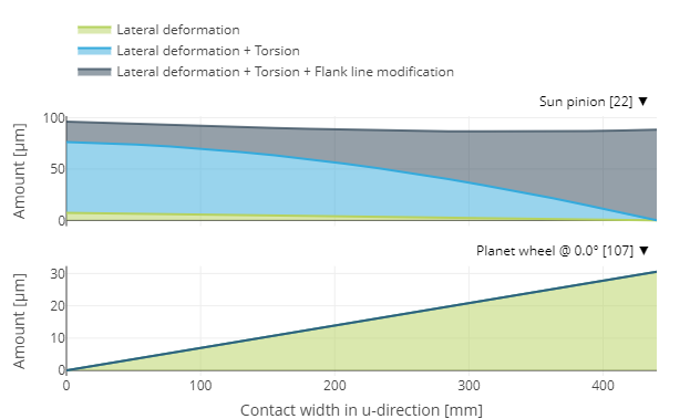
Figure 5: sun-planet mesh load distribution (left) and deformation amounts along the face width (right)
For planetary stages in which a gear modification that was designed using simplified methods is combined with low material reserves, damage patterns may occur with large pitting areas on the rotor-side end of the sun gear. Figure 6 shows an example of such a damage pattern, which can be attributed to a local overload, on a sun gear shaft from the main gearbox of a wind turbine in the 1.5 MW class, similar to the calculation model used.
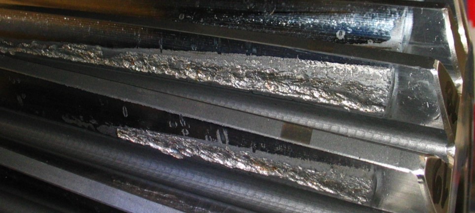
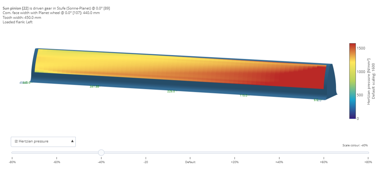
Figure 6: practical example of a damaged sun gear (top); 3D pressure distribution, Variant 3 (bottom)
Conclusion
The FVA-Workbench makes it easy to consider all relevant influencing factors in the design of gear modifications for planetary stages. This allows for weight- and cost-efficient design while also ensuring high operational stability.
References
[1] FVA Research Project 730 – Wind Turbine Drive Component Loads
[2] FVA Research Project 711 I: Integration of Elastic Casing Structures into Gear Design with RIKOR and Visualization of the Complete Transmission System in the FVA-Workbench
[3] FVA 364 I to V –LAGER 2 Subroutine
[4] FVA Research Project 909 – Rolling Bearing Calculation Transfer