
The Influence of Wheel Body Rim Width on Longitudinal Load Distribution
The goal of increasing the power density of a gear unit demands that extraneous material reserves can be detected and reduced to the necessary level. This requires knowledge of the influencing factors on the gear unit and the resulting loads. The following demonstrates the influence of the wheel body design and the required modification on the longitudinal load distribution, using an example two-stage reduction gearbox as commonly used in electromobility. The influence on the load and pressure distribution are also analyzed.
Wheel body calculations in the FVA-Workbench
The FVA-Workbench includes two different calculation options for the wheel body:
Option 1: The tooth contact is solved using a finite-element based approach. Complex geometries, such as wheel bodies of any shape, can easily be integrated into an FE calculation. The methods were developed and verified in FVA Research Project 484 V/VI. This allows detailed, realistic representation of single and multiple engagements.
Option 2: The wheel body is integrated into the system calculation using a reduced stiffness matrix. In this case, the gear is solved across the width only and then connected to the wheel body. Solving of the deformations, including calculation of the longitudinal load distribution, takes place in the shaft-bearing-gear system.
Positioning and meshing of the CAD wheel body
In the first step, the imported wheel body CAD geometry is correctly positioned to allow connection with the gear. The FVA-Workbench supports the user with numerous interactive tools which limit the amount of modeling effort required. CAD geometries can easily be reused and integrated into many different gearbox models.
The powerful FE mesher in the FVA-Workbench can even deal with complex geometries. In addition to linear and quadratic elements, the mesher also offers automatic component defeaturing which can automatically remove small, irrelevant bores. This simultaneously increases the mesh quality and reduces the number of elements, which ultimately results in increased calculation performance.
Calculation of the stiffness
The FE coupling nodes on the contact surfaces between the analytical gear and the FE wheel body, as well as between the shaft and the wheel body are automatically identified and highlighted in the 3D View for quick and easy review. These FE coupling nodes are required for determining a correct reduced stiffness matrix in the FVA-Workbench. This accurate and realistic stiffness matrix is then used for the wheel body in the system calculation, instead of the simplified full disc model.
Users who are already familiar with intensive FE component calculations will find that selections for the boundary conditions and the meshing have a significant influence on the calculation. The One Click FEM method ensures that reliable and reproducible results can be achieved, even without specialized FE knowledge.
Simple models – comparison with an FE full disc wheel
In the first experiment, the standard FVA-Workbench model of a full disc wheel is compared with an FE wheel body. A reduction gearbox, as commonly used in electric vehicles, is used as an example. The gear is designed so that the pressure does not exceed 1500 N/mm² with an input power of 200 kW.
For this calculation, a mesh geometry is chosen that is typical for electromobility. The maximum width of the wheel body corresponds to the width of the gears (25 mm).
| Wheel | Pinion | |||
| Normal pressure angle | αn | 20.00000 | 20.00000 | ° |
| Helix angle at reference diameter | β | -30.00000 | 30.00000 | ° |
| Number of teeth | z | 43 | 21 | - |
| Center distance | a | 75.000 | 75.000 | mm |
| Normal module | mn | 2.00000 | 2.00000 | mm |
| Transverse module | mt | 2.30940 | 2.30940 | mm |
| Addendum modification coeff. | x | 0.571790 | - | |
| Face width | b | 25.000 | 32.000 | mm |
| Tip diameter | da | 105.591 | 52.497 | mm |
| Transverse contact ratio | εα | 1.301 | 1.301 | - |
| Overlap contact ratio | εβ | 1.989 | 1.989 | - |
| Total contact ratio | εγ | 3.291 | 3.291 | - |
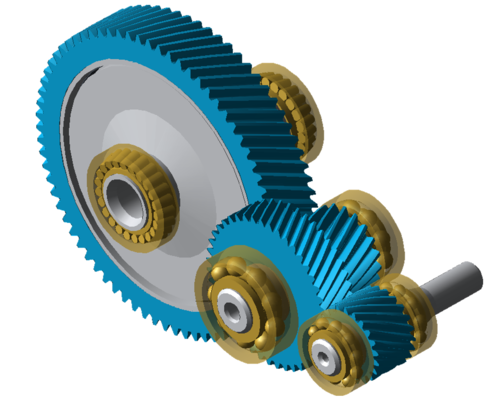
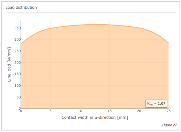
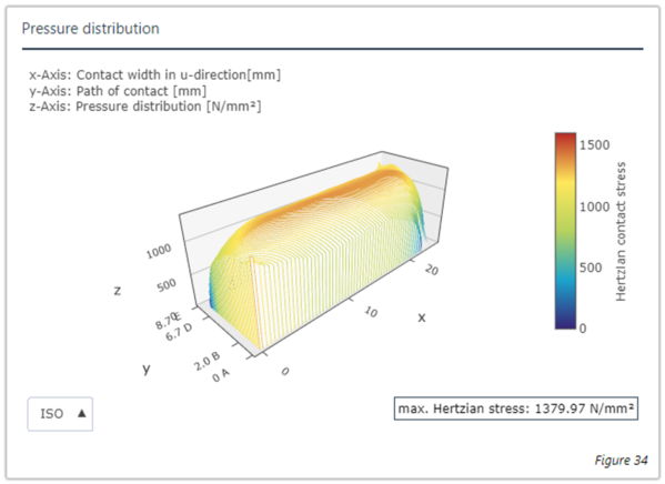

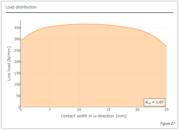
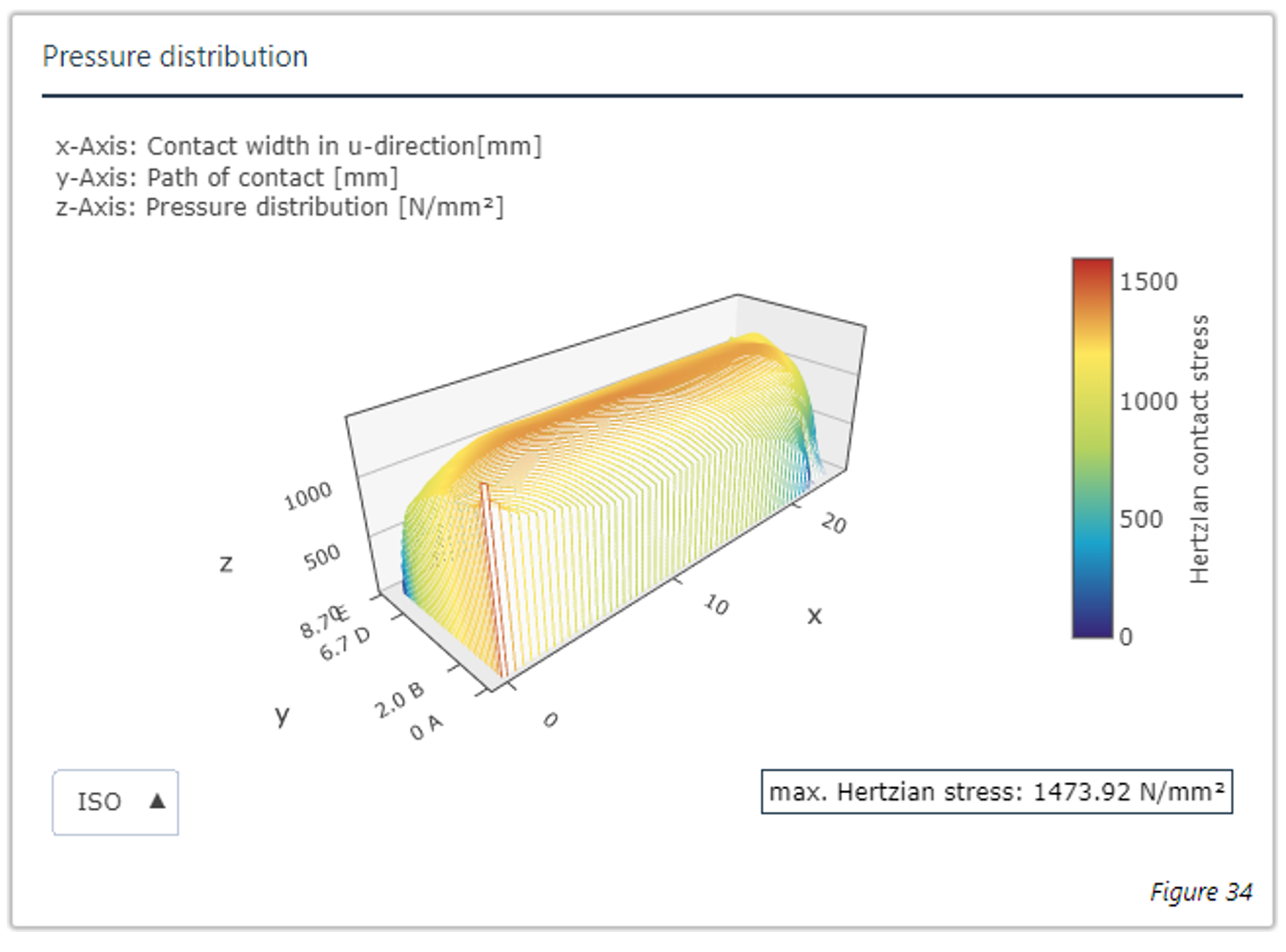
Figure 1: Results with the analytical full disc wheel body (left) and FE full disc wheel body (right)
The results of the calculation are shown in Figure 1. The results with the analytical full disc wheel body are on the left, the results of the FE full disc wheel body are on the right. This shows that the calculated load distribution over the face width and the results for the 3D load distribution are nearly identical.
Variation of the rim width of the wheel body
In the following, the influence of the wheel body on our example gear is determined by generating and comparing the results of the calculations with different wheel body geometries and rim widths. Additional bores are added for further weight reduction. These bores are positioned so that they are directly under the gear mesh in the calculation. This is a worst-case scenario that maximizes the influence of the wheel body.
The wheel body is designed as a parametric CAD component, and is generated for each calculation. The wheel rim is assumed to be 3* mn thick, so that its influence on the gear can be considered minimal (see ISO 6336-3 Figure 9). The hub is designed as an interference fit with a hub width that corresponds to the face width. The outer diameter of the hub is designed so that the full torque can be transmitted, even with the smallest rim width.
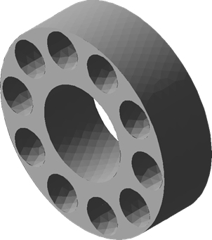
Variant 1: rim width 25 mm
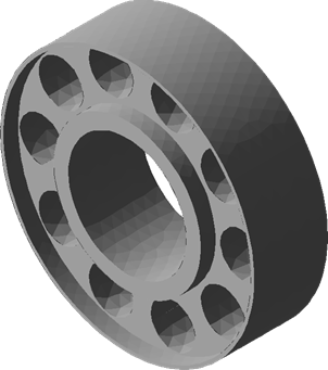
Variant 1: rim width 15 mm
Variant 1: rim width 10 mm
Variant 1: rim width 5 mm
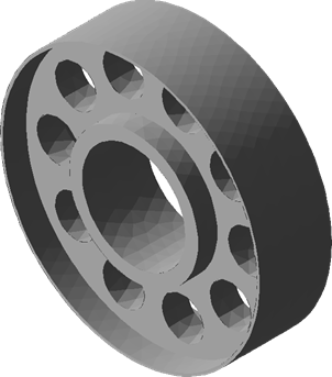
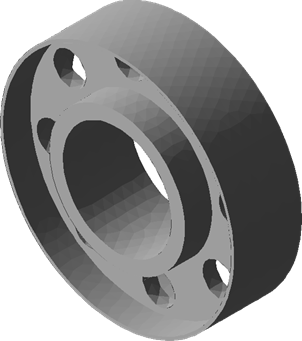
Figure 2: Wheel body with different rim widths
Influence of the rim width on the longitudinal load distribution
A weight savings of almost 50% can be achieved in Variant 4 due to the small rim width (5 mm). However, the simulation clearly shows that the wheel body is softer, and is therefore subject to greater deformation in mesh. This must be considered in the modification.
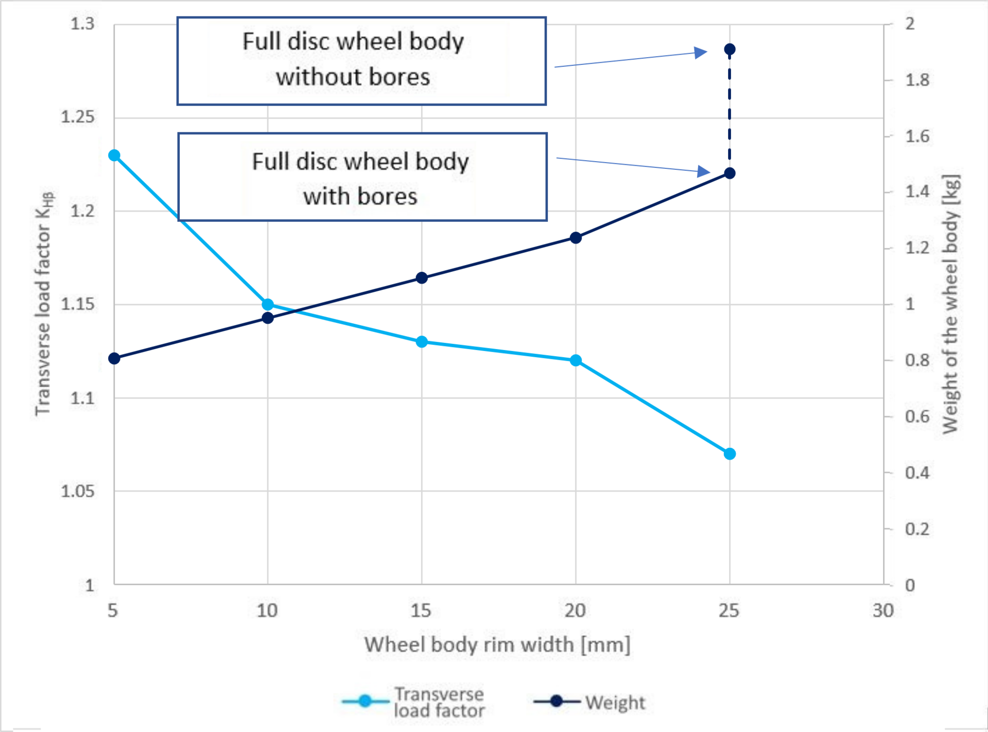
Figure 3: Weight and transverse load factor KHβ over the rim width
Figure 3 shows the weight of the wheel body and the resulting transverse load factor KHβ. The evaluation shows that the transverse load factor decreases rapidly as the rim width increases. No difference could be seen in the simulation between a full disc wheel body and a machined out wheel body with a rim width of 20 mm. However, strong deviations can be observed, which must be considered in the modification. The changes in the tooth contact are shown in Table 1. It can be seen that moderate rim widths only have a slight influence on the transverse load factor.
| Rim width | Weight [kg] | Rel. change | Transverse load factor K_Hβ | Max. pressure [N/mm²] |
| 25 (mit Bohrung) | 1,91 | 0 % | 1,07 | 1473.92 |
| 25 (ohne Bohrung) | 1,47 | -23 % | 1,07 | 1611.59 |
| 20 | 1,24 | -35 % | 1,12 | 1706.46 |
| 15 | 1,1 | -42 % | 1,13 | 1899.43 |
| 10 | 0,9 | -50 % | 1,15 | 2188.90 |
| 5 | 0,8 | -58 % | 1,23 | 3171.81 |
However, with a rim width of 20 mm, the limit value of 1500 N/mm² is locally exceeded by a small amount at the maximum pressure. From a rim width of 15 mm, a single-sided pressure overload occurs, which could lead to pressure damage on the flank. The additional deformations resulting from the wheel body stiffness can be corrected by a simple helix angle modification. The proposed modification in the FVA-Workbench shows the required modification amount for the load distribution. However, when changing from drive to coast operation, it is important to note that the torque reverses with the same direction of rotation. In this case, the trailing flank comes into contact. The gear tilts in the opposite direction due to the wheel body stiffness. Therefore, the rear flank must be modified differently than the front flank.
Conclusion
The power density of a gear unit can be increased relatively simply via a small rim with bores. This can be used to achieve significant weight savings on the gear. However, it also leads to a softer construction. With One-Click FEM in the FVA-Workbench, even novices can perform quick and reliable FE calculations. The guided calculation process helps to quickly and easily consider the desired effects. The influence of the wheel body stiffness is clearly visible with complex wheel bodies. The assumption of a full disc wheel is therefore no longer acceptable. The additional deformations can easily be calculated with the FVA-Workbench. The proposed gear modification takes the additional stiffness into account, so that the gear modification can easily be determined to ensure optimal operation. When designing the modification to consider the wheel body stiffness, all anticipated operating points must be taken into account. In particular, the change from drive to coast operation can lead to unacceptably high pressures in the edge area of the gear.