Calculation of the gear load carrying capacity according to standard methods (ISO 6336, DIN 3990, AGMA 2101, etc.) is based on simplified assumptions for load distribution.
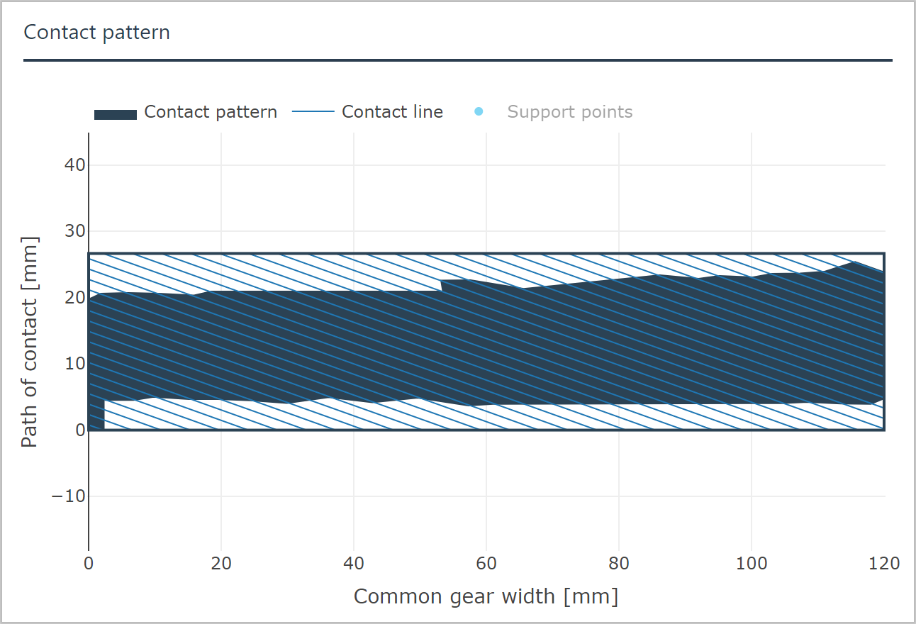
For very large ratios or unfavorable profile modifications, these simplified assumptions may lead to unreliable designs. Detailed consideration of the actual local loads across the tooth flank is required to identify these cases. For this purpose, the load distribution for the entire mesh along the lines of contact is calculated. Determination of the stiffness of the individual contact points is essential.
The FVA-Workbench includes both an analytical method according to FVA 30 as well as an FE-based method according to FVA 127. The load distribution along the contact lines is determined using the influence coefficient method.
This load distribution is the basis for a detailed analysis of damage mechanisms and for the optimized microgeometry design.
Dimensioning with consideration of gear damage
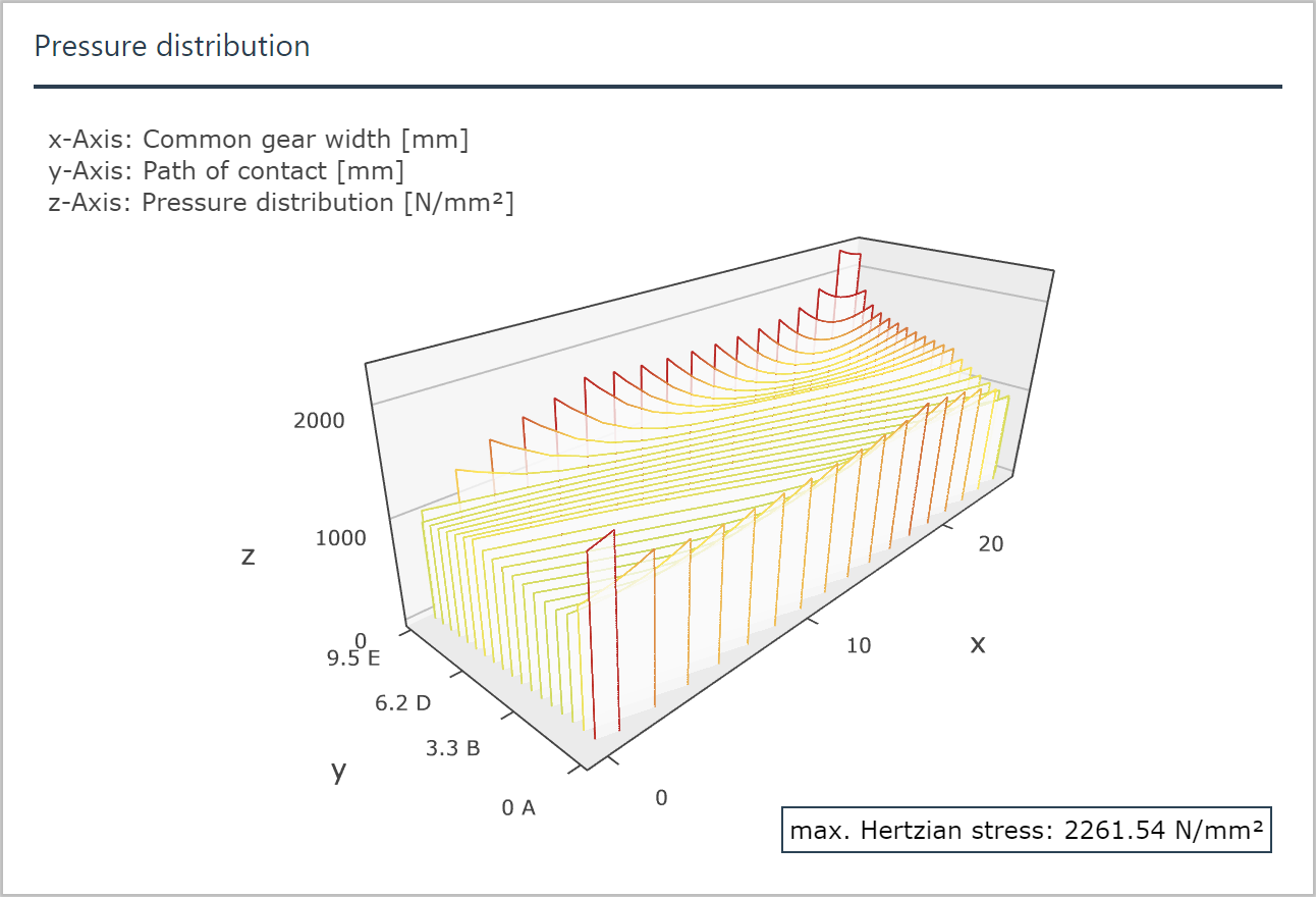
Pitting
The flank load carrying capacity of a cylindrical gear is essentially determined by the contact pressure. The risk of pitting of a gear can be assessed by analyzing the local pressure distribution.

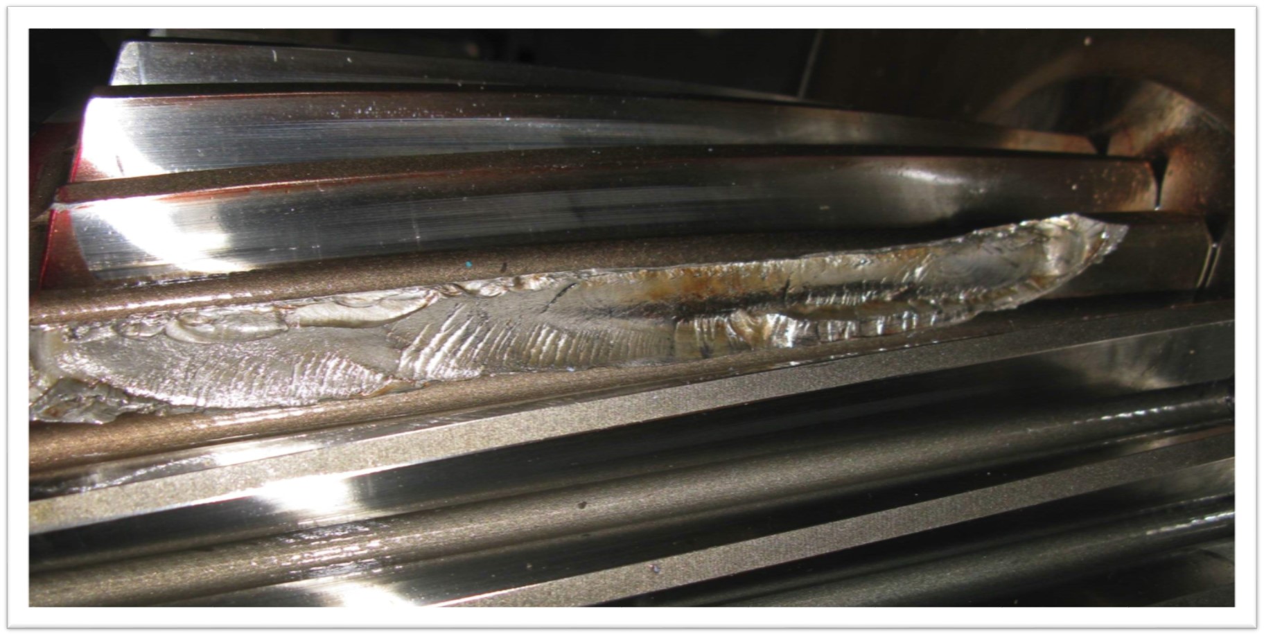
Scuffing
The flash temperature distribution is essential for the evaluation of the scuffing load capacity. In the FVA-Workbench, the local flash temperature is calculated from the load distribution according to ISO 6336 part 20/21.
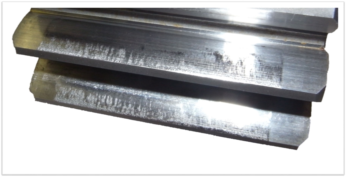
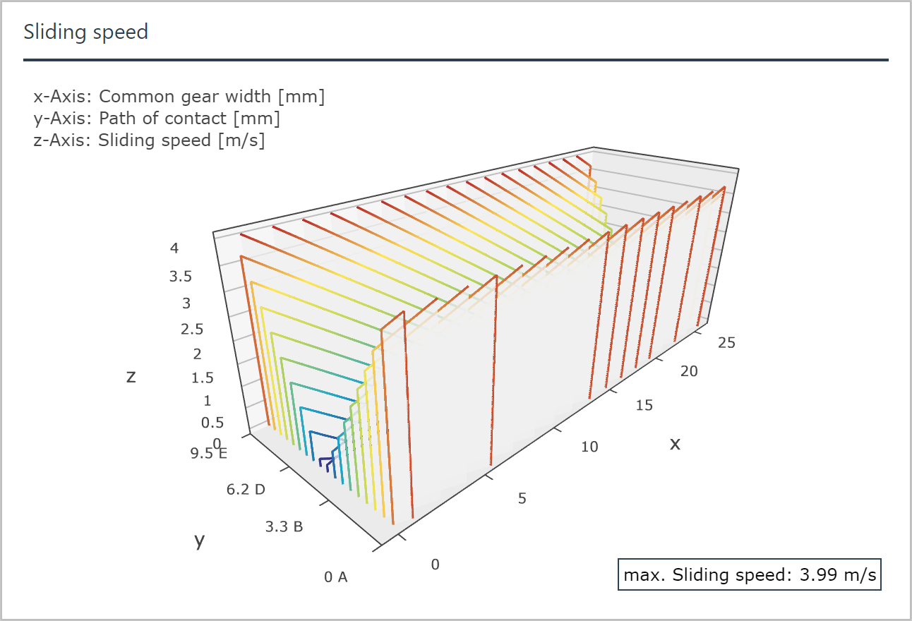
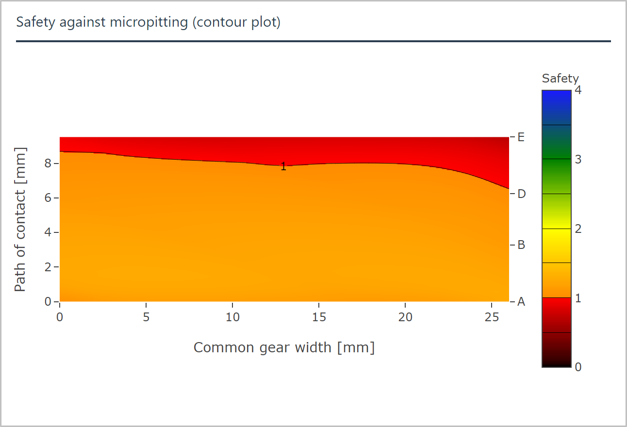
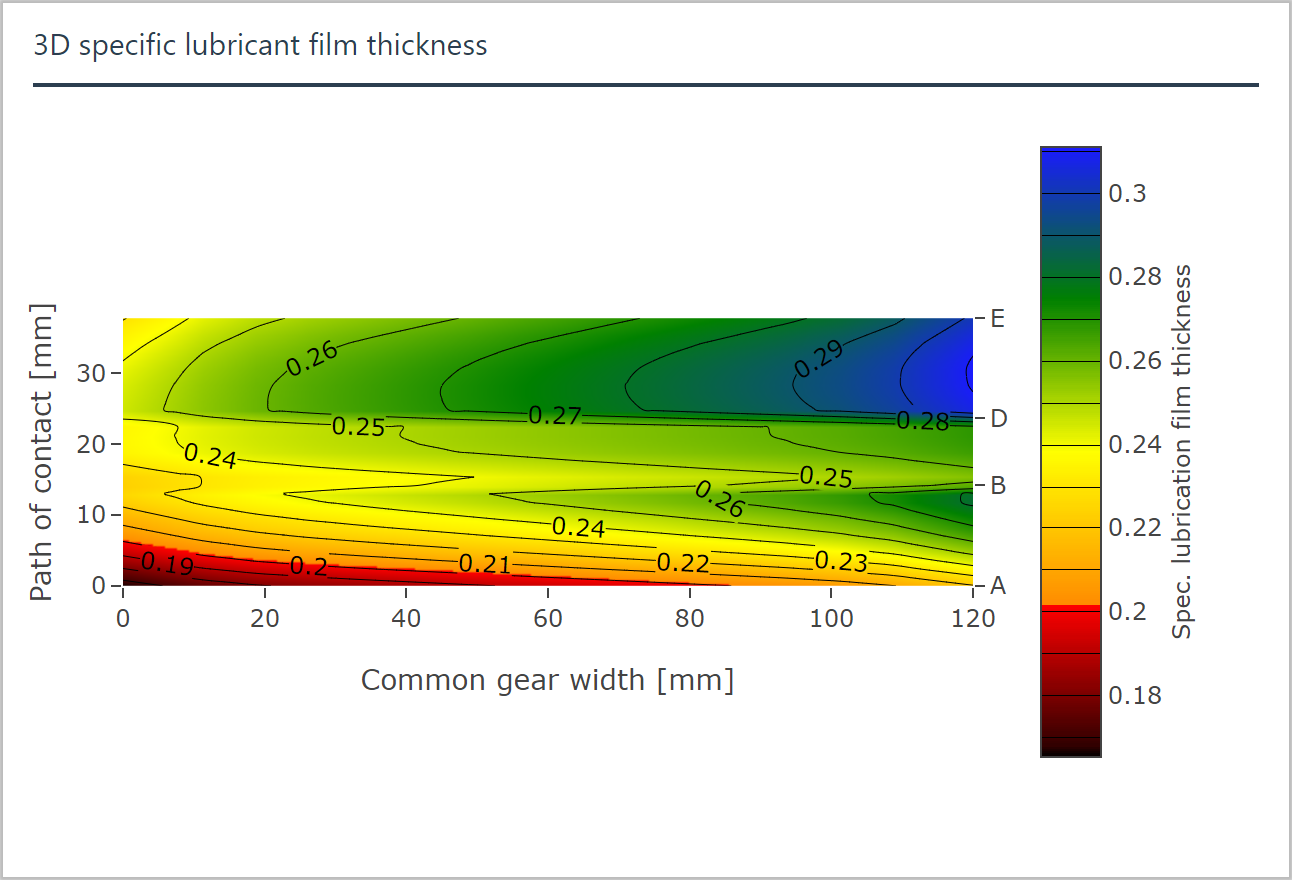
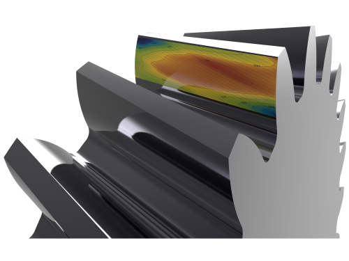
Micropitting
With the FVA-Workbench, the local micropitting resistance can be calculated according to ISO TR 15144. Intermediate results such as the local lubricant film thickness and sliding speed are also output for better evaluation of the calculation results.

Flank fracture
In the FVA-Workbench, the risk of flank fracture of cylindrical gears can be estimated according to ISO 6336 Part 4.
Tooth root fracture
For gears where a closer examination of the tooth root stress is required, the local tooth root stress can be calculated based on the boundary element method.

Damage avoidance with optimized flank modifications
The types of damage mentioned above can be avoided with suitable flank modifications. The FVA-Workbench supports the user by calculating a proposed topological correction. The user can choose various correction criteria (e.g. uniform pressure distribution). In addition to specification of standard corrections, flank topographies that have been measured or calculated from a manufacturing simulation can also be imported and evaluated.
Calculation results (selection)
Click to enlarge