The calculation approaches in the FVA-Workbench are based on analytical methods that have been known for decades in the drive technology industry and validated by innumerable FVA e.V. research projects. These solutions deliver high-performance calculations while at the same time also producing high-quality results.
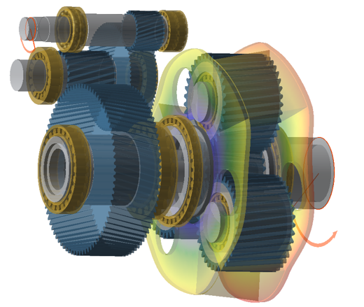
However, not all bodies can be analytically described with sufficient accuracy. For this reason, casings, planet carriers, wheel bodies, and shafts in particular are considered using finite element analysis in the FVA-Workbench. Generally speaking, the FE approach is applicable for complex component geometries which can no longer be represented within the validity range of the analytical approaches (Figure 1). In the following, this difference will be explained using the example of the FEA shaft calculation approach of the FVA-Workbench.
In the FVA-Workbench, shaft deformation is calculated using the Timoshenko beam theory. In this approach, the bending deformation according to the Euler/Bernoulli method is combined with consideration of the shear deformation. The following limitations remain when using the Timoshenko approach:
For the majority of common gear shaft geometries these limitations do not lead to any practice-relevant deviations compared to the actual shaft deformation. However, if more complex geometries are used, or to check whether the limitations of the Timoshenko beam theory lead to significant deviations for a particular shaft geometry, shaft deformations can also be calculated using FEM features of the FVA-Workbench. Shafts generated within the FVA-Workbench can be internally meshed for this purpose.

For more complex geometries, shafts exported from CAD programs can be read and meshed. The meshing and determination of contact nodes with the rest of the gearbox model is largely automated. The user navigation has been designed for maximum efficiency, so that FE shafts can be modeled, meshed, and calculated as quickly as possible. Users can create a full-featured mesh for FE calculation in just a few clicks, without any special FE knowledge. This automatic meshing is possible because the deformation analysis performed places significantly lower demands on the mesh size than a stress analysis.
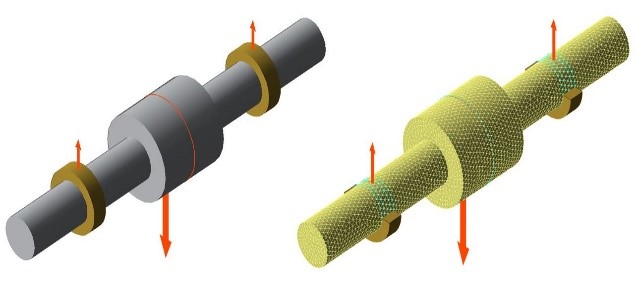
In the following, a stepped shaft will be used as an example to explain the difference between the FE calculation and calculation using the Timoshenko beam method. The comparative calculation was performed using a simplified shaft geometry (Figure 2). The shaft has dual support bearings and is loaded with a single force at the center.
The outer diameter of the central shaft section will be varied for the comparison. The conditions will range from 1 (smooth shaft) to 3.5 (very strong shoulder). The base diameter of the shaft is 50 mm.

In order to couple the stiffness of the FE elements with the analytical approaches, the stiffnesses are reduced to the coupling points. For shafts, the coupling points are the bearings, gears, load application points, or couplings. In the reduction, a stiffness matrix is determined for the coupling that describes the deformation behavior at the coupling points as well as the complete consideration of the entire FE component. Therefore, only the coupling points are visible in the calculation.
The deformations of the entire component can be calculated from the loads on the coupling points in a post-processing step. This procedure makes an extremely high-performance calculation possible taking the influence of all deformations in the gear into consideration. The influences on the gear are experimentally proved in FVA research project 592 II.
Figure 3 shows the maximum shaft deflection over the ratio of the outer diameter of the middle segment relative to the diameter of the adjacent shaft sections.
For smooth shafts it can be seen that the analytical method produces the same result as the FE calculation. However, from a diameter increase of 1.25, the analytical solution calculates a lower shaft deflection for this shaft geometry than the FE calculation. From a 3-fold increase in the diameter of the middle section, the FE calculation produces a constant 23% lower shaft deflection than the analytical approach.
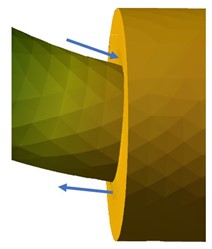
In this case, the difference can be attributed to two causes. It is partially due to the uneven distribution of the flow of forces over the cross-section, and partially due to the curvature of the cross-section of the shaft in the area of the diameter step (Figure 4). As described above, neither of these effects are considered in the Timoshenko analytical approach.
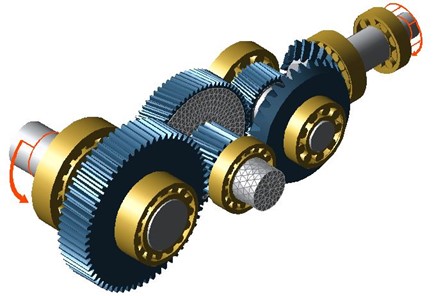
The differences in the shaft deflection calculation methodology described above can also be seen in practical gearbox models, such as the bevel-cylindrical gear unit shown in Figure 5.
Here, the following variants of the load distribution across the face width of the output stage were performed for the intermediate shaft:
Figure 6 shows the load distribution across the face width for both calculated variants. Although the influence on the shaft deflection is not as strong here as in the theoretical example in Figure 2, a significant increase of the face load factor KHß from 1.22 to 1.27 can be observed for the FE calculation.


The detailed geometry of notches, such as feather keys, shaft shoulders with undercuts, and rectangular grooves, are accurately displayed in the 3d model to provide the user with graphical feedback on the specified geometry (Figure 7). These extensions have also been made with regard to the implementation of FKM guidelines for calculation of shaft safeties in the current version FVA-Workbench 6.0, which supplements the shaft safety calculations according to DIN 743.