Bevel Gear Wheel Body Design
Basics of bevel gear calculations in the FVA-Workbench
The FVA-Workbench offers various options for bevel gear calculations. Simple methods use common ISO, DIN, or AGMA standards, ship classification society specifications, and FVA calculations. These approaches utilize equivalent cylindrical gears, and can therefore be easily applied without specific production machine and detailed geometry specifications. However, they do not represent the exact bevel gear geometry. This is precisely where local bevel gear simulations come in. In contrast to simple methods, these are based on a precise manufacturing simulation and consideration of all points in the meshing area. With this local approach, all relevant influences can be considered, such as shaft misalignment, the position of bevel gears relative to each other, and the surrounding stiffness. In addition to simple safety parameters, local load capacity analysis including local damage accumulation or damage progress calculations can also be performed.
This article focuses on using local gear calculations to improve modeling.
Wheel body design in the FVA-Workbench
The surrounding stiffness has a significant influence on the calculation of the load distribution of bevel and hypoid gears. The stiffness of the surrounding bearings, the shaft, the teeth, and the wheel body are all taken into consideration.
Previously, the stiffness of the wheel body was approximated in the FVA-Workbench via an elastic half-space. In FVA Research Project FVA 223 XVI “Method for including the stiffness of complex wheel bodies in the load distribution calculation and its implementation in BECAL“ (IMM, TU Dresden, Prof. Dr. Schlecht; CAD, Universität Bayreuth, Prof. Dr. Rieg), methods were developed to accurately supplement the stiffness of the wheel body using a suitable FE model. With this model, bores in the wheel body, the position at which the wheel is mounted to the shaft, and the geometry of the wheel body can all be precisely considered.
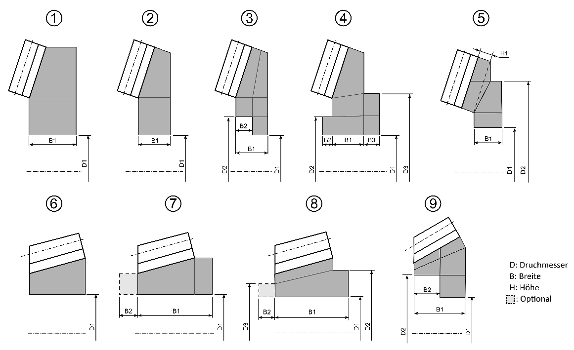
Consideration of wheel body deformation early in the design phase with configurable standard wheel bodies: In the early design phase, the precise wheel body geometry has often not yet been finalized. For this reason, wheel bodies can be parametrically generated in the first step. All important parameters can be defined from a selection of 9 standard wheel bodies and 6 different clamping options. This makes it possible to quickly and easily make initial estimations of the influence of the wheel body in the very early phases of the project, avoiding time-consuming and costly changes to the design. Numerous diagrams and help texts assist with the input process in the FVA-Workbench. Wheel bodies can be exported as CAD components to support the progress of the project. This provides engineers with a basic design that only needs to be detailed.
Configurable standard wheel bodies
To ensure good meshing quality, variants 1-5 are recommended for typical ring gear wheel bodies, and variants 6-9 are recommended for typical pinion wheel bodies. By default, variant 6 is used for the pinion and variant 1 is used for the ring gear.
Configuration of the clamping areas
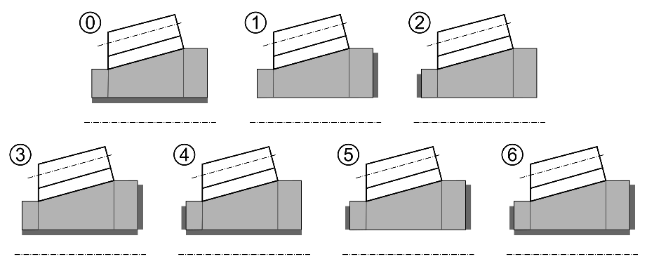
By default, heel clamping (1) is selected for the pinion, and hub clamping (0) is selected for the ring gear. Toe clamping (2) is another option, and options 3 - 6 can be used for combined clamping areas.
Consideration of the deformation of complex wheel body geometries in the advanced development process
All wheel bodies can be imported and processed as CAD models. The first step is the positioning, which ensures that the component later sits in the right place and makes the CAD design independent from subsequent calculations. During positioning, the CAD model is cropped to ensure that the cut surface fits precisely on the gear, and that any teeth on the wheel body are cut out. Mathematically speaking, the positioning process corresponds to a coordinate transformation. Graphical support helps to ensure that no errors occur during this process.
The component is meshed in the next step. The FVA-Workbench monitors the meshing quality and issues a warning if too many distorted or unsuitable elements arise. The FEM quality checker can be used to easily identify where unsuitable elements occur. These can either be removed from the CAD model or resolved by increasing the meshing quality. Finally, the coupling nodes are defined. The snapping of the coupling nodes is an automated process which marks all FEM nodes that contact the gear or shaft.
Consideration of wheel body deformation in local load carrying capacity calculations
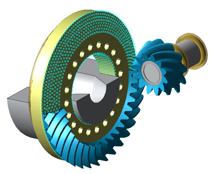
The local load carrying capacity calculation consists of multiple calculation steps, which are automatically processed. It is based on the exact geometry of the bevel gear teeth, including all topological modifications. This exact geometry is either calculated from the manufacturing simulation based on the machine settings, or imported by reading the description of the surface as a point cloud (3D neutral data). The relative position deviations under load, which occur due to deformation of the housing, shaft deflection, and bearing deflection during operation, are taken from the system calculation. The tooth contact is simulated using the exact geometry and the determined relative deviations. The contact ratios calculated in this way can be visualized as ease-off, contact pattern, and rotational error. So-called Klaff (gape) dimensions describe the contact distances between the teeth along the contact lines, taking the working variation, multiple engagements, and early engagement into account. This is used to calculate the load distribution. The stiffness ratios of bevel gears with elastic wheel bodies are represented by the sum of BEM and FEM influence coefficients. The wheel body elasticity is contained in the FEM influence coefficients. Another new feature is that the coupling influences of all teeth in the engagement are considered and added to the influence coefficient matrix for modeled wheel bodies. Finally, the local stress and the root stresses over the face width are derived from the local load distribution calculation and the contact ratios, and the corresponding local load carrying capacity values and safeties are determined.
The influence of wheel body design on flank load distribution
Influence of the width of the crown gear wheel body
The width of the wheel body has a direct influence on the stiffness of the gear, and therefore on the result. In the following, the influence of the width of the wheel body on the pressure distribution and the tooth root stress will be discussed. For this purpose, a parametric model will be built in the FVA-Workbench using a standard wheel body, which can be very easily adapted and recalculated. In this model, the width of the gear wheel body will be varied, and the results compared against each other. Toward the bottom, the width of the wheel body will be limited so that the FE meshing requires a minimum rim thickness from a section modulus. A thinner wheel body can only be achieved with a custom design.
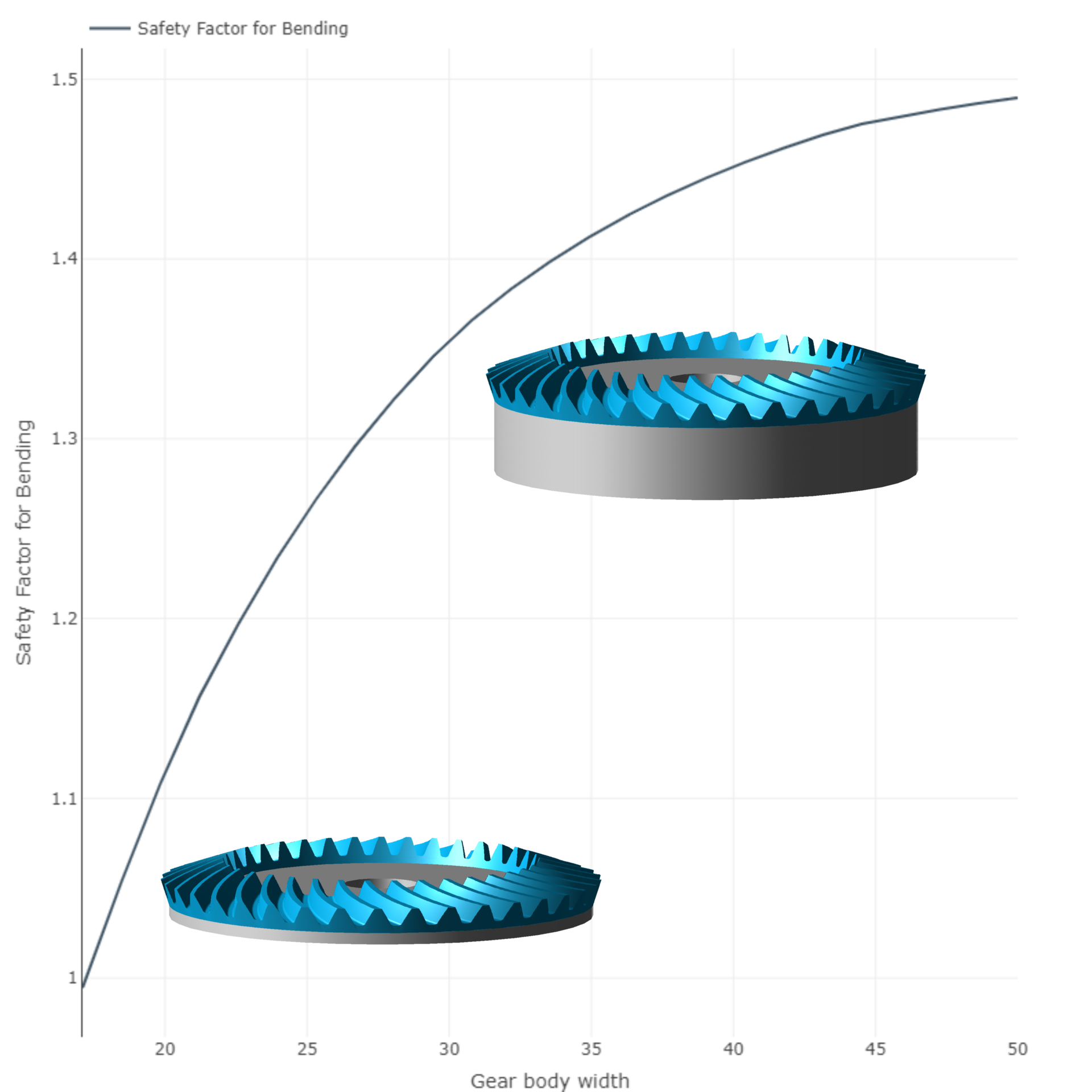
The wheel body geometry for the thickest and thinnest variant are shown in Figure 3. The turquoise line represents the pinning boundary at the hub. This is where the wheel body is fixed to the shaft.
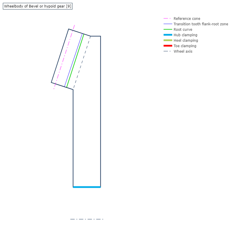
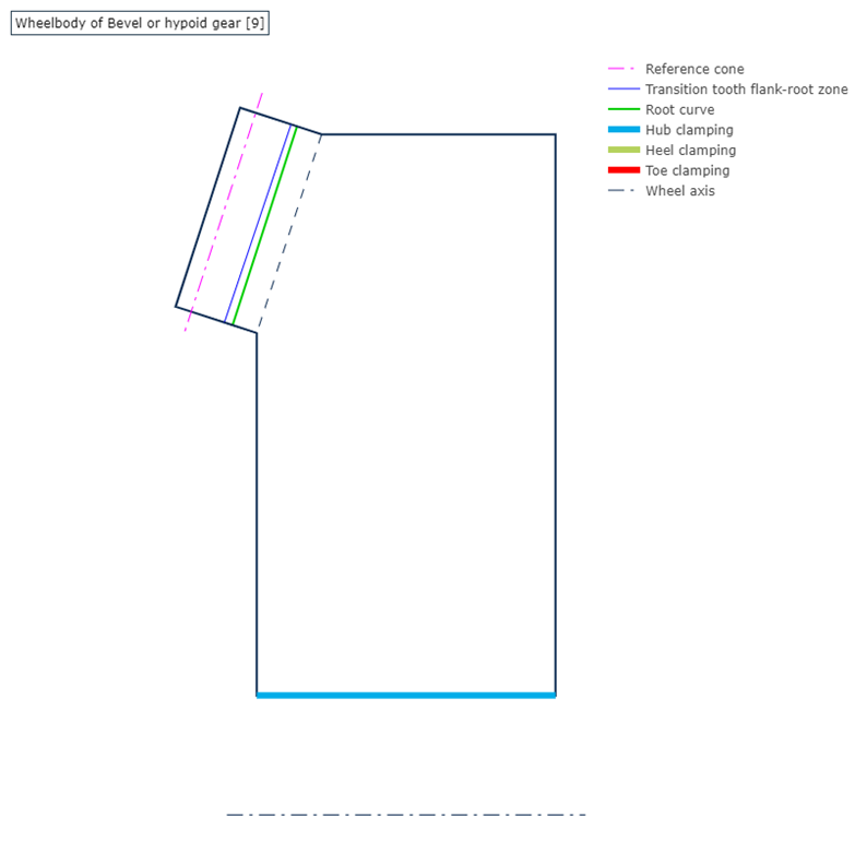
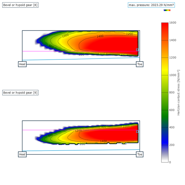
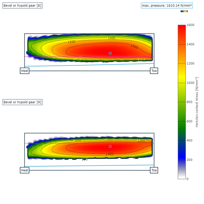
Figure 6 and 7 show the pressure distribution on the tooth flank for a wheel body with a width of 17.1 mm and 50 mm. Direct comparison clearly shows that the teeth no longer come into optimal mesh due to the low stiffness of the gear body, resulting in edge loading with excess stress. This indicates the strong influence of the wheel body on the entire operating behavior.
Figure 8 plots the tooth root safety over the width of the wheel body. As the width of the wheel body increases, it becomes clear that the tooth root safety is reduced. When considered in this way, an optimum value can be determined to ensure sufficient safety.
Easily consider the influence of the wheel body with the FVA-Workbench
The influence of the wheel body stiffness for bevel gear meshing can be completely described with the FVA-Workbench. “Just-in-case“ overdimensioning is no longer necessary. The bevel gear module can simply and precisely simulate where critical operating conditions occur and appropriate design solutions to avoid them.
Comparing the pressure distribution of both wheel bodies clearly illustrates that the thinner design leads to greater edge loading. Therefore, it is essential to take the wheel body stiffness into account in gear design.
The option to define parametric wheel bodies in the FVA-Workbench makes it easy to consider the influence of the wheel body early in the product development phase. This can be used to avoid both modification costs and overdimensioning.


