Influence of the Load-Dependent Center Distance
High power density, combining maximum power with the lowest possible mass, requires the use of lightweight materials such as aluminum, magnesium, or plastic. However, these materials have significantly lower stiffness compared to steel. As the mass of a shaft increases by the square of its diameter, even a small reduction in the diameter can reduce the overall mass. All of these measures lead to increased softness of the system, and therefore to more severe deformations.
In tooth contact, the meshing forces always act along the path of contact at an angle to the center distance corresponding to the pressure angle. The meshing forces act on the shafts and the bearing system, leading to deformation of the system in the direction of the meshing force.
The deformations acting on the gear teeth can be obtained by dividing the shaft bending line into perpendicular sections in the direction of the center distance. Generally speaking, only the deformations arising perpendicular to the mesh are of interest, as these can lead to misalignment of the gears. These deformations should be compensated for with standard modifications, since misalignment can lead to increased loads and significantly reduced service life.
The deformations in the direction of the center distance cannot be corrected and do not have a direct effect on the load carrying capacity, as would be the case if the gears were tilted toward each other. However, this type of deformation acts similar to a change in the center distance. Therefore, the portion of the shaft bending line in the direction of the center distance is referred to in this article as the load-dependent center distance.
Definition of the load-dependent center distance
The load-dependent center distance leads to a change in the mesh, as the gears are either pulled out of or pushed into the mesh, depending on the system. This results in a change to the length of the path of contact and the contact ratio.
The model
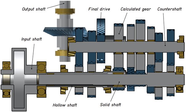
The following example will discuss the influence of the load-dependent center distance on the meshing of a dual-clutch gearbox. Figure 1 shows the cross-section of the 3D gear model in the FVA-Workbench gear design software. The gearbox consists of the double clutch at the gearbox input, which engages either the hollow shaft for the odd gears or the solid shaft for the even gears. Idler gears are mounted on the countershaft. The power is transmitted out of the gearbox via a bevel gear stage.
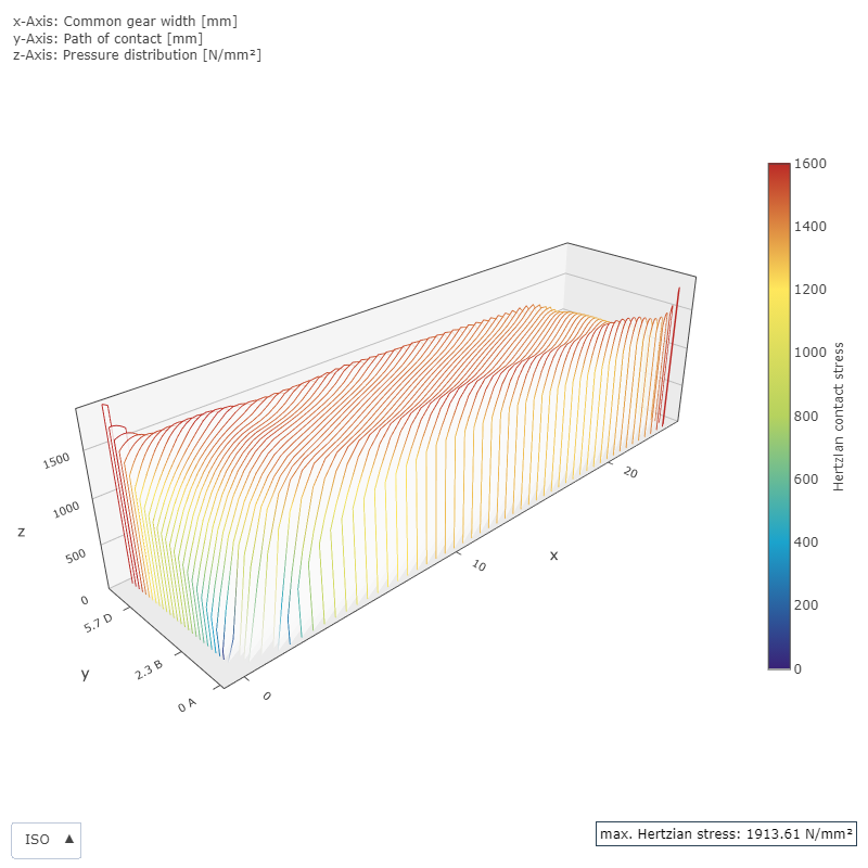
Since the greatest deflection is to be expected in the center of the countershaft, the second gear is considered the critical gear and is discussed in the example below. The gearing is designed so that the pressure is as uniform as possible and does not exceed a maximum value of 1500 MPa. The applied modification ensures that no load or pressure peaks are to be expected on the flank.
Influence on the load carrying capacity
The contact ratio determines many key characteristics of the gearing. It indicates the average number of teeth across which the load is distributed. A contact ratio of 1 indicates that exactly one pair of teeth is always in mesh, while a contact ratio of 1.5 indicates that 2 pairs of teeth are in mesh across half of the path of contact. The meshing forces can thus be distributed across multiple teeth, which is beneficial for the load carrying capacity.
Due to the flexible design of the countershaft, the meshing forces push the teeth away from each other, which reduces the contact ratio. The average number of teeth transmitting the load is reduced correspondingly. This has a negative effect on the safety factors. In this example, the design criteria were defined exclusively by the pressure, and the safety factors according to ISO 6336 (without consideration of a load spectrum) are correspondingly low.
Table 1 shows that the flank safety factor is slightly reduced by taking the load-dependent center distance into account. However, the root safety factor increases significantly. This is due to the fact that the lever arm for the meshing force is increased, so that the load is smaller. However, the bending moment arm on the tooth increases, as the overall load is higher. In this case, the load-dependent center distance has a positive effect, but there can also be cases in which the tooth root safety is reduced. Thus, it is essential to take the load-dependent center distance into account.
|
| With load-dependent center distance | Without load-dependent center distance | ||
|
| Pinion | Wheel | Pinion | Wheel |
Flank safety factor | SH | 0.68 | 0.68 | 0.72 | 0.72 |
Root safety factor | SF | 0.94 | 0.78 | 0.52 | 0.52 |
Table 1: Gear safety factors with and without the load-dependent center distance
Influence on the load and pressure distribution
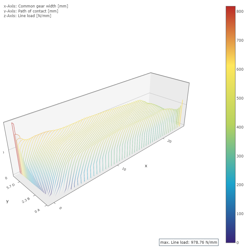
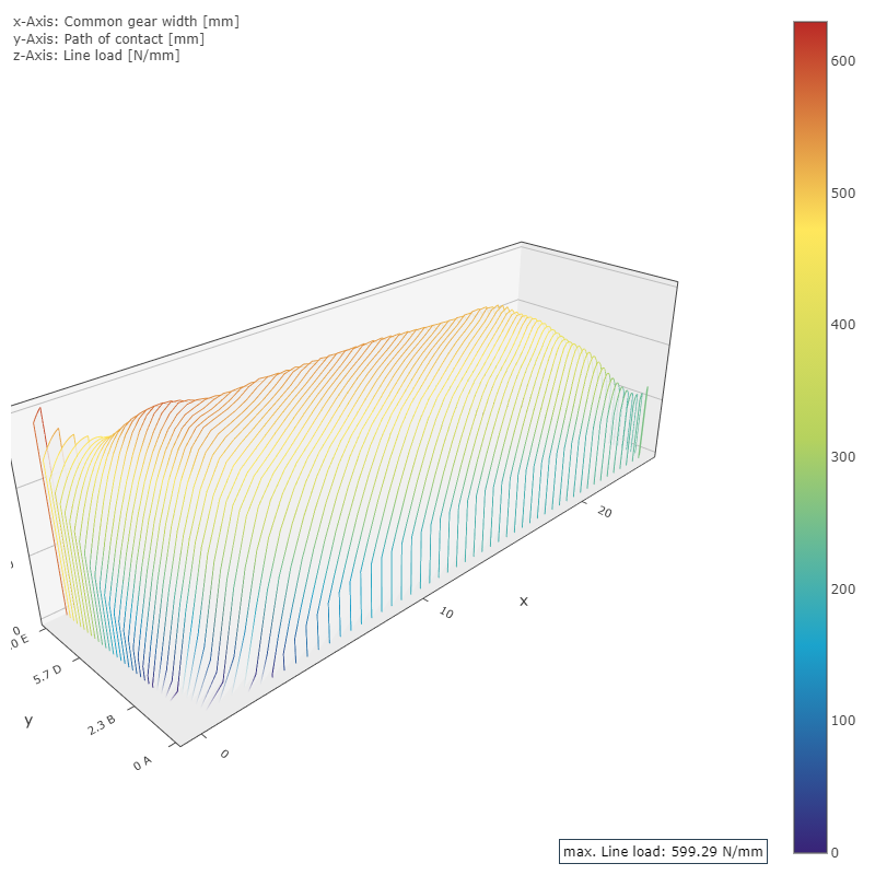
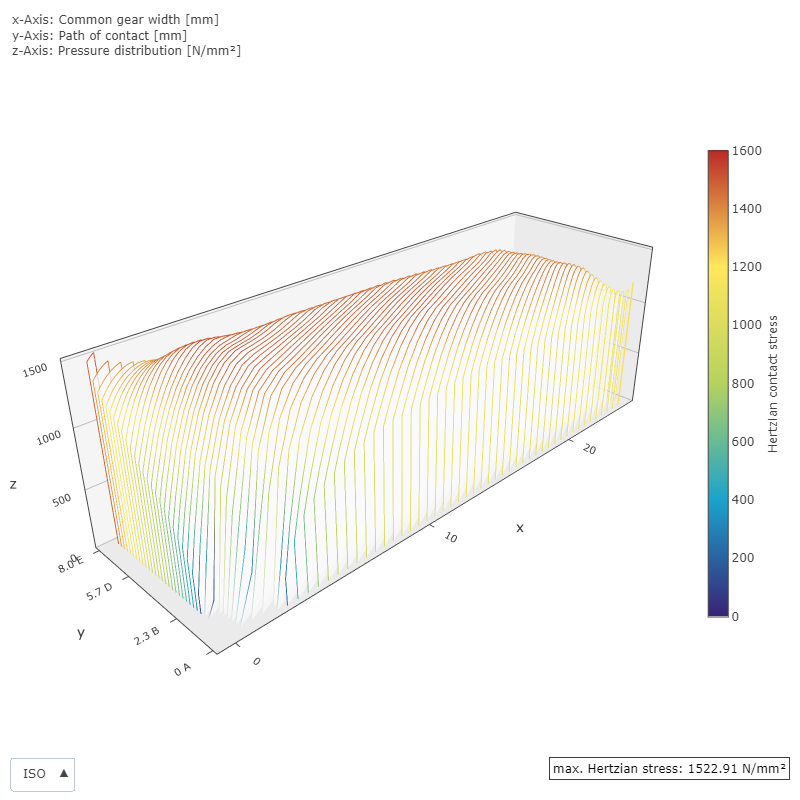
The microgeometry of the gear plays a key role in the load and pressure distribution. Figure 2 clearly shows that the gear was designed without taking the influence of the load-dependent center distance into account. If this influence is considered, the load distribution in the direction of the mesh is no longer uniform, but increases significantly.
Influence on the noise excitation
One evaluation criterion for the noise excitation is the transmission error and excitation level. Transmission error occurs as a result of fluctuating stiffnesses in the gear and different loads, depending on the mesh position. The excitation level is formed from a weighted sum of the individual frequencies of the gear, with an emphasis on the audible frequencies. This is described in FVA 133 – Overlap ratio, FZG – TU München.
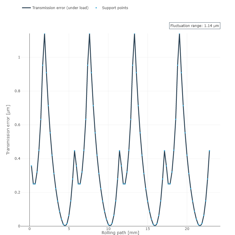
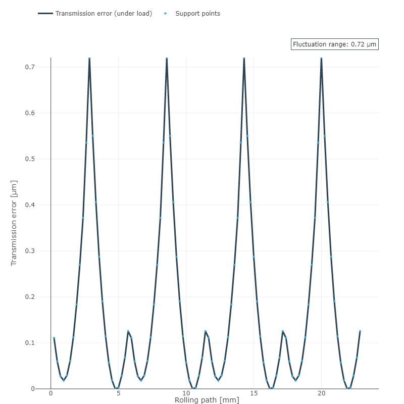
The influence of the load-dependent center distance becomes even clearer if the transmission error is calculated from the represented load distribution. The range of variation of the transmission error increases by more than 50%, while the excitation range increases from 16.79 dB to 19.35 dB. It can therefore be assumed that this gearbox is significantly louder than one in which the load-dependent center distance is considered in the design.
Figure 4 shows a simulation of the transmission error with and without the load-dependent center distance from an FVA-Workbench results report.
FVA 264 offers a method for further consideration of the tooth root stress, in which the local tooth root stress over the mesh can be solved using the BEM method. Figure 5 shows a simulation of the tooth root stress with and without the load-dependent center distance from an FVA-Workbench results report.
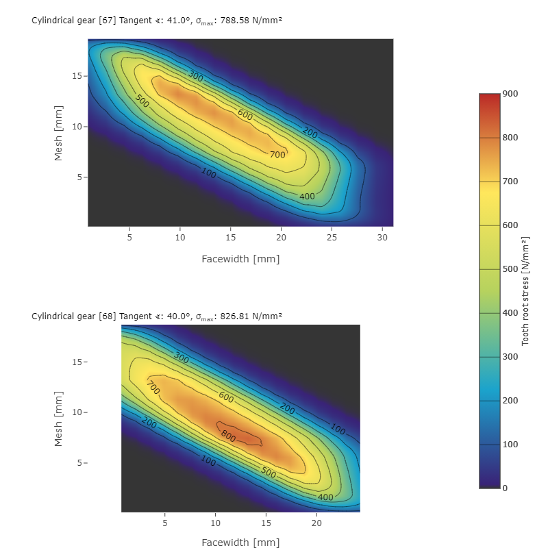
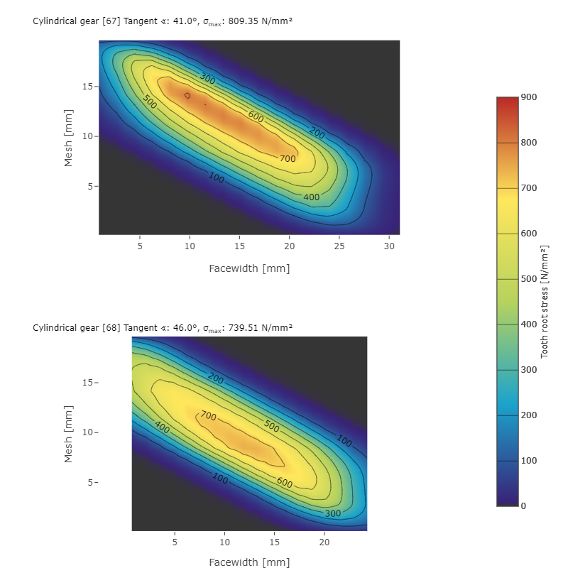
Analysis shows that the tooth root stress on the wheel increases from 739 N/mm² to 826 N/mm² when the load-dependent center distance is taken into account. At the same time, the stress on the pinion decreases slightly from 809 N/mm² to 788 N/mm².
Consideration of the load-dependent center distance in the FVA-Workbench
This example features a particularly soft design. As a result, the influence of the load-dependent center distance is very prominent. In particular, a significant increase in the tooth root safety can be observed. However, this is not a general trend; it only applies to this example. Therefore, consideration of the load-dependent center distance is always recommended.
Considering the local flank parameters, such as pressure or transmission error, a significant influence of the load-dependent center distance can be observed. Pressure increases of around 400 N/mm² can be seen at the transition between the tip relief and the flank. This shows that the influence of the load-dependent center distance must be taken into account when designing modifications. The noise excitation of the gearbox can be evaluated from the transmission error. The more than 50% increase in the transmission error underscores the necessity of accounting for the load-dependent center distance. In this case, it becomes clear that the applied modification is no longer adequate.
With the FVA-Workbench, the load-dependent center distance is always considered.

